Chapter 1
Force and moment equilibria
1.1 Statics, rigid bodies and force systems
Statics is the subdivision of mechanics concerned with the forces that act on solid bodies at rest under equilibrium conditions. The solid body can be thought of as a collection of matter within an identifiable boundary, and it is important to distinguish notions of rigid and deformable bodies.
| Rigid body (Chapters 1-3) |
| Do not change its shape under internal or external forces |
| Forces and moments can be plotted as a function of a position |
| ”Nothing” happens within material |
| Deformable body (Chapters 4-12) |
| Can change its shape under internal or external forces |
| Inherent material properties must be accounted to find deformation |
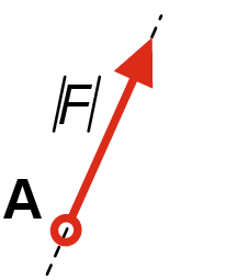
Mechanics heavily relies on the notion of force. We all intuitively understand this concept, and in physics, force usually represents internal or external action on the body. From a practical point of view, any force can be represented as a vector \(\v {F}\), and it is fully determined by its magnitude \(|F|\), line of action, direction and contact point (Fig. 1.2).
Fig. 1.3a shows a rigid body subjected to multiple forces. In engineering mechanics, every combination of forces acting on the rigid body is called a force system. Graphical representation of force vectors enables the replacement of multiple forces acting on the body by a single equivalent force called the resultant of the system. Besides one important exception that will be discussed later, every force system can be reduced to resultant via a simple step-by-step procedure:
- Pick two forces acting on the body;
- Shift both forces along their corresponding acting line to the point of intersection;
- Replace these forces by their resultant (vector sum of the initial forces);
- Start all-over, until only one force is left;
- The remaining force is the resultant of the initial force system.
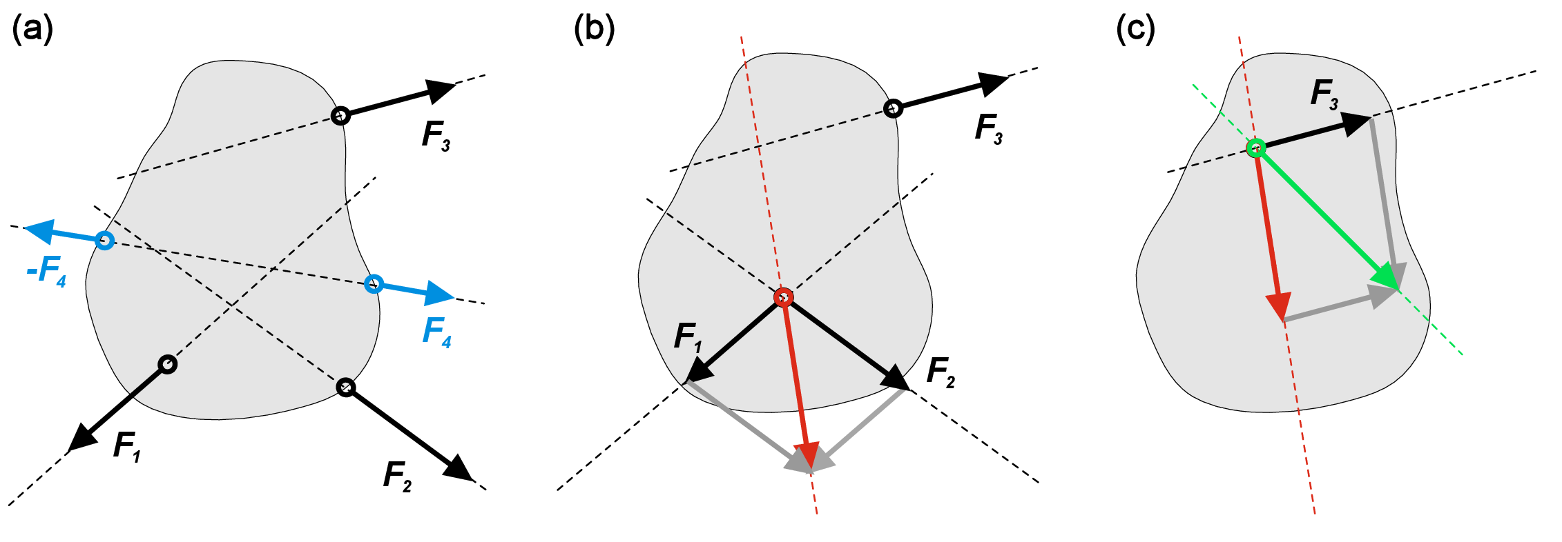
Fig. 1.3 illustrates this procedure for arbitrarily selected force system. First, blue forces \(F_4\) cancel each other since they share the line of action, have the same magnitude and opposite directions (Fig. 1.3a). Then, by sliding the forces \(F_1\) and \(F_2\) to the intersection point of their corresponding action lines, we can get the resultant of \(F_1\) and \(F_2\) (red vector in Fig. 1.3b). Then, the same procedure for this new resultant and initial force \(F_3\) gives us the resultant of the whole system (green vector in Fig. 1.3c).
1.2 Force couples and moments
Two forces (Fig. 1.4a) cannot be reduced to a single resultant if they have
- Same magnitude
- Parallel lines of action
- Opposite directions
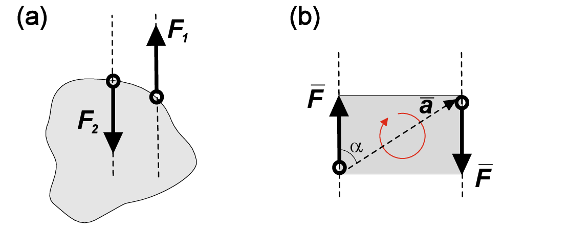
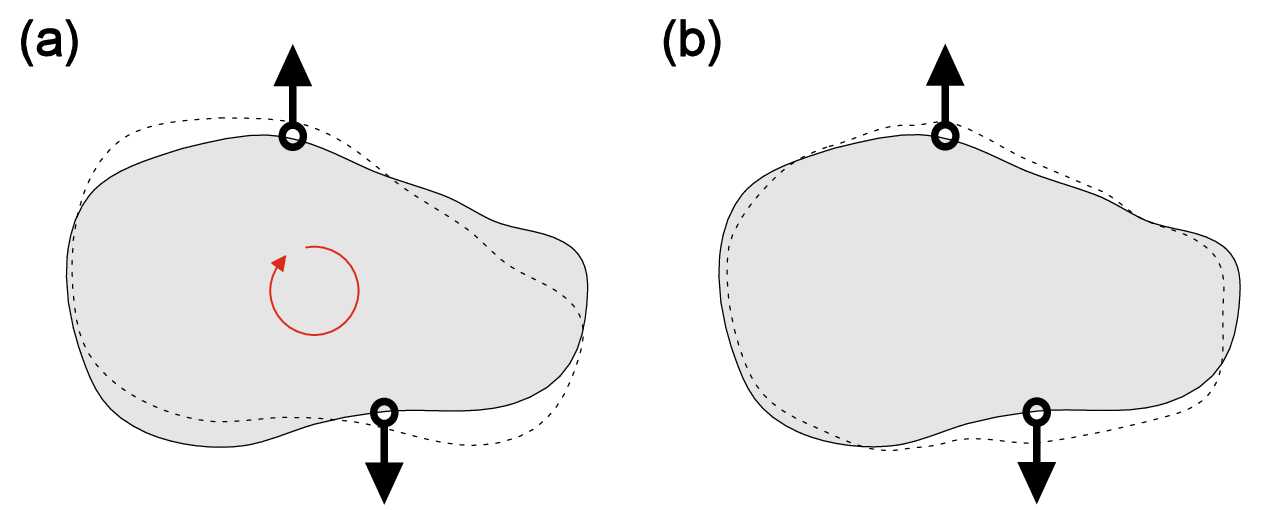
Such a force system is called a force couple or pure moment. If a resultant represents the translation movement of the rigid body, a pure moment corresponds to rotation. The moment of force couple is defined by direction of rotation, magnitude and distance between corresponding lines of action (Fig. 1.4b). Note that force moment is not fixed at any certain contact point and can be moved freely over the whole body as long as the direction of rotation and magnitude of the moment are conserved. In a general 3D system, we can define the moment as cross product of two vectors \begin {equation} \v {M}=\v {a}\times {\v {F_1}}, \end {equation} where \(\v {a}\) is a vector connecting the contact points of two vectors in force couple, and \(\v {F_1}\) is one of these vectors as shown in Fig. 1.4b. The vector representation of moment enables us to define moment area \(|\v {M}|\) as \begin {equation} |\v {M}|=|\v {a}\times {\v {F_1}}|=|\v {a}||\v {F_1}|\sin {\alpha }, \end {equation} where \(\alpha \) is the angle enclosed by \(\v {a}\) and \(\v {F_1}\). Note that by definition, the moment area is always positive, however a specific sign can be assigned to the moment depending on its direction.
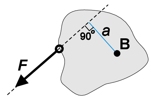
A single force will exert a moment at a certain point B outside from its line of action (Fig. 1.5). This moment of single force is defined as a product of the force magnitude \(|F|\) and the perpendicular distance \(a\) between point B and the line of action (\(M=a|F|\)). Note that the contact point of \(F\) and action point B cannot coincide. The moment of a single force is sometimes called a torque. It is important not to mix up moments generated by force couple and by a single force.
| The force couple |
| May induce a pure rotation of a body |
| Does not have a reference point |
| The single force |
| May induce a translation of the body |
| Exert a moment in a reference point outside its line of action |
Now we understand how to work with forces and moments, and it is time to define the last word in the definition given at the beginning of this chapter – equilibrium.
A 2D force system is in equilibrium if the sum of all forces \(F_i\) and the sum of all moments \(M_i\) equal zero. \begin {equation} \sum _{i}{F_i}=0 \quad \text {and}\quad \sum _{i}{M_i}=0 \end {equation}